How to Pick the Perfect Boost Converter for Your Needs
Choosing the right boost converters requires careful consideration of several factors to ensure optimal performance for your application. Start by evaluating the following key aspects:
Voltage: Ensure the boost converters support input voltages between 5V and 45V DC and provide the desired output voltage.
Efficiency: Look for efficiency ratings between 80% and 95% to minimize energy loss.
Current: Verify the boost converters can handle the maximum load current without overheating.
Size: Confirm the physical dimensions of the boost converters align with your design's space constraints.
Cost: Balance your budget with the need for quality and reliability.
Aligning these specifications with your project requirements ensures the boost converters deliver reliable performance. Use tools like the Converter Control Rank Metric (CCRM) to compare models based on efficiency, cost, and deployment needs. This approach helps you select a boost converter that meets both technical and contextual demands.
Input and Output Voltage Requirements for Boost Converters
Understanding Input Voltage Range
When selecting a boost converter, understanding the input voltage range is crucial. The input voltage range defines the minimum and maximum voltages the converter can accept. For example, many dc-dc converters operate within a range of 4.5V to 42V, as shown in industry benchmarks. This range ensures compatibility with various power sources, such as batteries or solar panels.
A well-defined input voltage range helps maintain stable operation under fluctuating conditions. For instance, in applications like DC motors, a closed-loop control system adjusts the boost converter's output to match speed requirements. This adjustment ensures consistent performance even when the input voltage changes.
| Input Voltage Range (V) | Description |
|---|---|
| 20 | Minimum input voltage |
| 75.84 | Maximum input voltage |
| 80 | Ideal state voltage |
By carefully evaluating the input voltage range, you can ensure the converter meets your application's power conversion needs.
Determining Output Voltage Needs
The output voltage requirement is another critical factor. It refers to the steady output voltage the boost converter must deliver to power your device. Whether you're designing a dc voltage boost converter for LED lighting or a boost dc-dc converter for industrial equipment, the output voltage must align with your device's specifications.
For example, a boost converter used in a dc-dc application might need to step up a 12V input to a 24V output. This step-up ensures the device receives adequate power for optimal performance. Additionally, the output voltage range can be fixed or adjustable, depending on the converter's design.
| Parameter | Value Example |
|---|---|
| Maximum Input Voltage | 42V |
| Minimum Input Voltage | 4.5V |
| Output Voltage Range | Fixed or Adjustable |
Matching the output voltage to your device's requirements ensures reliable operation and prevents damage to sensitive components.
Ensuring Voltage Regulation Compatibility
Voltage regulation compatibility ensures the boost converter maintains a steady output voltage despite changes in input voltage or load current. This feature is essential for applications requiring precise power delivery, such as medical devices or communication systems.
Key specifications like line regulation and load regulation determine how well the converter handles variations. For instance, line regulation measures the change in output voltage caused by input voltage fluctuations. Similarly, load regulation evaluates the output voltage's stability under varying load conditions.
| Specification | Description |
|---|---|
| Line Regulation | Change in output voltage caused by a change in input voltage. |
| Load Regulation | Change in output voltage for a change in output current. |
| Soft Start | Prevents overshoot at startup by ramping output voltage gradually. |
| Undervoltage Lockout | Turns off the converter if the input voltage drops below a safe threshold. |
By ensuring voltage regulation compatibility, you can achieve consistent performance and protect your devices from power-related issues.
Load Current and Power Needs in Boost DC-DC Converters
Calculating Load Current Accurately
Accurately calculating load current is essential for designing a reliable dc voltage boost converter. Load current refers to the amount of current your device draws during operation. To compute this, you can use equations that relate input voltage, output voltage, resistance, and duty cycle. For example:
| Equation | Description |
|---|---|
| Vo = Vin1 - d(1) | Relates output voltage to input voltage and duty cycle. |
| Io = VoR(3) | Defines output current using output voltage and resistance. |
| IL = Iin = VoVinIo = 11 - dVoR(5) | Links inductor current, input current, and output parameters. |
| ΔiL = VinL × d × Ts | Calculates peak-to-peak ripple current in the inductor. |
These equations help you determine the load current based on your dc-dc converter's specifications. For instance, if your boost dc-dc converter operates with a 12V input and a 24V output, you can calculate the current drawn by the load using the resistance value. This ensures your converter delivers sufficient power without exceeding its limits.
Matching Power Ratings to Application Demands
Matching the power ratings of your boost converters to your application demands ensures optimal performance. Power ratings include the maximum voltage and current the converter can handle. For example, if your application involves powering LED lighting, you need a dc voltage boost converter capable of stepping up the voltage while maintaining efficiency.
Case studies show how temperature changes affect power ratings. For instance:
| Parameter | Value (when temperature changes from 60 to 50 °C) |
|---|---|
| PV Output Power | Data from Table 7 |
| Output Voltage | Data from Table 7 |
| Duty Ratio | Data from Table 7 |
| Conversion Efficiencies | Data from Table 7 |
By analyzing these parameters, you can select a boost dc-dc converter that meets your application's power needs while maintaining efficiency under varying conditions.
Avoiding Overloading Risks
Overloading occurs when the load current exceeds the converter's capacity, leading to overheating or failure. To avoid this, choose a converter with a higher current rating than your device's maximum load. Figures like efficiency versus output current plots reveal how load current impacts performance. For example:
Figure 17 shows the transient response of a boost converter when a 1 ampere load is applied, highlighting voltage sag and recovery.
Figure 18 demonstrates efficiency variations with load current, helping you understand power loss.
Figure 30 graphs efficiency at different supply voltages over a range of output currents, showing the relationship between load current and power needs.
By considering these factors, you can prevent overloading and ensure your boost converters operate reliably under all conditions.
Efficiency and Thermal Management in Boost Converters
Importance of High Efficiency Ratings
High efficiency in boost converters ensures minimal energy loss during operation. This directly impacts the performance and longevity of your device. When a converter operates with high efficiency, it reduces heat generation, which helps maintain stable operation. For instance, efficiency ratings above 90% are common benchmarks for reliable converters.
| Condition | Efficiency (%) |
|---|---|
| Full Load | 94.2 |
| Maximum Efficiency | 95.64 |
| Various Duty Cycle | >92 |
| Maximum at 30 W | 95.64 |
These numbers highlight the importance of selecting a boost dc-dc converter with high conversion efficiency. A converter with such ratings ensures optimal performance while minimizing power loss. You should always prioritize efficiency ratings when choosing a dc voltage boost converter for your application.
Techniques for Effective Heat Dissipation
Heat dissipation plays a critical role in maintaining the high operational efficiency of boost converters. Without proper thermal management, excessive heat can degrade components and reduce the lifespan of your device. To address this, you can use techniques like thermal modeling and cooling solutions.
| Section | Description |
|---|---|
| Power Loss Analysis | Discusses equations and preliminary power losses for thermal modeling in DC-DC converters. |
| Thermal Simulations and Analysis | Focuses on simulations validating cooling solutions under real operating conditions. |
These methods help you evaluate and improve the thermal behavior of your converter. For example, thermal simulations allow you to test cooling solutions before implementation, ensuring they meet the demands of your application. By incorporating these techniques, you can achieve better heat dissipation and maintain the efficiency and thermal expansion balance in your system.
Selecting Components for Optimal Thermal Performance
Choosing the right components is essential for managing heat and ensuring your boost converter operates efficiently. Thermal interface materials (TIMs) and MOSFETs with high thermal conductivity are excellent options. Studies show that adding 10% tungsten to TIMs increases thermal conductivity by 74.2%.
| Description | Value | Unit |
|---|---|---|
| Thermal conductivity increase due to 10% Tungsten in TIM | 74.2 | % |
| Thermal conductivity at room temperature | 22.82 | W/m.K |
| Thermal conductivity before addition | 13.1 | W/m.K |
To assess the effectiveness of TIM samples in reducing conduction losses, you can use the formula:
$$\text{P}{\text{cond}}= {{\text{I}}{\text{G}}}^{2} \times {\text{R}}{\text{DS}\left(\text{ON}\right)}$$
Here, ${\text{P}}{\text{cond}}$ represents conduction losses in a MOSFET.
By selecting components with high thermal conductivity, you can minimize heat buildup and improve the overall performance of your dc-dc system. This ensures your boost converter delivers reliable power under varying conditions.
Size and Structural Constraints of DC Voltage Boost Converters
Evaluating Physical Dimensions and Space Requirements
When selecting a dc voltage boost converter, you must evaluate its physical dimensions to ensure it fits within your design's space constraints. Compact designs often require converters with smaller footprints, especially in portable or embedded systems. Manufacturers typically provide detailed datasheets with dimensions, helping you determine if the converter aligns with your project's requirements.
For example, a boost dc-dc converter used in wearable devices must be small enough to fit within the limited space while still delivering the required performance. You should also consider the height of components, as taller designs may interfere with enclosures or other hardware.
PCB Layout Considerations for Compact Designs
A well-designed PCB layout is critical for achieving optimal performance in compact dc-dc systems. Following best practices can help you minimize parasitic effects and electromagnetic interference (EMI).
Minimize parasitic resistance, capacitance, and impedance to improve efficiency.
Use proper grounding techniques to reduce EMI.
Keep power components close together and use short, wide routing traces to lower parasitic effects.
Avoid routing signal traces underneath the module unless sandwiched between ground planes to prevent noise coupling.
Strategically place ground planes to provide effective return paths for high-speed signals.
These guidelines ensure your boost converters operate efficiently, even in space-constrained designs. Proper PCB layout not only enhances performance but also reduces the risk of overheating and noise issues.
Adapting to Space-Limited Applications
Space-limited applications demand innovative solutions to maintain performance without compromising size. For instance, continuous conduction mode (CCM) boost converters with advanced control techniques, such as fractional-order PID and neural networks, can optimize power factor correction. This approach reduces EMI and minimizes the need for extensive filtering, making it ideal for compact designs.
Active power factor correction (PFC) topologies are another effective solution. These converters produce smoother input current waveforms, which enhance efficiency and reduce noise. By leveraging advanced control methods, you can achieve better performance in environments where space is at a premium.
When designing for space-limited applications, focus on selecting components and layouts that balance size, efficiency, and thermal management. This ensures your dc voltage boost converter meets the demands of your application without sacrificing reliability.
Additional Features in Boost DC-DC Converters
Protection Mechanisms for Reliable Operation
Reliable operation depends heavily on robust protection features. Boost converters often include mechanisms that safeguard your system from potential damage. These features ensure safe operation and enhance the longevity of your device.
Hot Swap Controllers: These controllers allow seamless insertion and removal of devices without interrupting power flow. They protect against overcurrent conditions and provide real-time monitoring, reducing downtime.
Shutdown Function: This feature disables the converter to minimize battery drain. It completely disconnects the load from the battery during shutdown, making it ideal for portable applications.
Auto Discharge: This mechanism discharges output capacitors during shutdown, which is particularly useful for microcontroller-based systems.
Testing protective devices ensures they operate correctly under various conditions. Proper operation is essential for maintaining system reliability and preventing failures.
By incorporating these protection features, you can ensure your boost dc-dc converter delivers consistent performance while safeguarding your application.
Switching Frequency and Noise Reduction
Switching frequency plays a critical role in reducing noise and optimizing the size of your dc voltage boost converter. Higher frequencies allow for smaller inductors and capacitors, enabling compact designs without compromising power density.
Noise Sources: Noise in switching regulators originates from high and low-frequency components. Proper measurement techniques help identify these sources effectively.
Reduction Strategies: Layout techniques, filtering, and component selection minimize noise. For example, placing components close together and using short traces reduces electromagnetic interference (EMI).
Compact Designs: Transitioning to higher-frequency systems reduces the size of EMI filters and energy storage components. This results in more power-dense systems suitable for space-limited applications.
Higher switching frequencies not only reduce noise but also enable miniaturization, making your converter more suitable for modern compact designs.
By focusing on switching frequency and noise reduction strategies, you can enhance the application suitability of your boost converters.
Application-Specific Features for Specialized Projects
Specialized projects often demand unique features tailored to specific requirements. Multi-function boost converters have evolved to meet these needs, offering adaptability and efficiency.
For example, in electric vehicle battery chargers, bidirectional power flow enables energy transfer between the battery and the grid. Hybrid energy storage systems benefit from enhanced efficiency in power conversion, ensuring optimal performance under varying conditions.
| Feature | Description |
|---|---|
| Low-EMI Mode | Reduces electromagnetic energy, ideal for sensitive applications. |
| Power Good Output | Provides control for cascaded power supply components. |
| Voltage Regulation | Generates stable output voltages, adjustable or fixed. |
These features make your dc voltage boost converter versatile and capable of handling diverse operational demands. By selecting converters with application-specific features, you can achieve better performance and reliability in specialized projects.
Cost and Budget Considerations for Boost Converters
Balancing Cost with Performance and Reliability
When choosing a boost converter, balancing cost with performance and reliability is essential. You should evaluate how much you are willing to spend while ensuring the converter meets your technical needs. Boost converters often cost more than other types of power converters. This higher cost reflects their ability to provide stable voltage and high efficiency in demanding applications.
To make an informed decision, compare the features of different models. Look for converters that offer advanced protection mechanisms, high efficiency, and robust thermal management. These features may increase the initial cost but can save you money in the long run by reducing energy loss and preventing device failures.
Evaluating Long-Term Value and Durability
Investing in a durable boost converter can provide long-term value. A reliable converter reduces the need for frequent replacements, saving you money over time. You should consider the build quality and materials used in the converter. High-quality components ensure better performance and a longer lifespan.
Durability also depends on how well the converter handles environmental factors like heat and vibration. Models with effective thermal management systems and sturdy enclosures are ideal for harsh conditions. By focusing on durability, you can maximize the return on your investment and ensure consistent performance for years.
Comparing Affordable Options Without Compromising Quality
Finding an affordable boost converter without sacrificing quality requires careful research. Start by identifying your application's specific requirements. Then, compare models within your budget that meet these needs. Look for converters from reputable manufacturers, as they often provide reliable products at competitive prices.
You can also explore models with fewer advanced features if your application does not require them. For example, a basic converter with moderate efficiency may suffice for a low-power device. By prioritizing essential features, you can find a cost-effective solution that delivers reliable performance.
Tip: Always check user reviews and technical specifications before purchasing. This helps you avoid low-quality products and ensures you get the best value for your money.
Choosing the right boost converters requires careful attention to voltage, current, and efficiency. These factors directly impact your project's performance and reliability. For example, input voltage sets the starting point for conversion, while output voltage ensures compatibility with your device. Efficiency minimizes energy loss and extends the lifespan of your system.
| Factor | Importance | Example Values |
|---|---|---|
| Input Voltage | Determines the starting point for conversion. | 3.3V, 5V, 12V |
| Output Voltage | Must meet project requirements for device operation. | 24V, 48V |
| Load Current | Affects the choice of converter based on power needs. | Varies by application |
| Efficiency | Impacts energy wastage and device longevity. | Higher efficiency preferred |
Size, features, and cost also play a vital role in selecting the best converter. Compact designs suit space-limited applications, while advanced features like protection mechanisms enhance reliability. Balancing cost with performance ensures long-term value.
Evaluate your requirements thoroughly before making a decision. This approach helps you select a converter that aligns with your technical needs and budget, ensuring optimal results for your application.
FAQ
What is a boost converter, and why do you need one?
A boost converter is a device that increases (boosts) a lower input voltage to a higher output voltage. You need it when your application requires a stable, higher voltage than the available power source provides, such as in LED lighting or battery-powered devices.
How do you calculate the efficiency of a boost converter?
You calculate efficiency using this formula:
Efficiency (%) = (Output Power / Input Power) × 100
For example, if the output power is 90W and the input power is 100W, the efficiency is 90%.
Can a boost converter handle fluctuating input voltages?
Yes, most boost converters can handle fluctuating input voltages within their specified range. Look for features like voltage regulation and undervoltage lockout to ensure stable performance under varying conditions.
What happens if you overload a boost converter?
Overloading a boost converter can cause overheating, reduced efficiency, or permanent damage. Always choose a converter with a current rating higher than your device's maximum load to avoid these risks.
Are smaller boost converters less efficient?
Not necessarily. Smaller boost converters can achieve high efficiency with advanced designs and components. However, compact designs may generate more heat, so proper thermal management is essential to maintain performance.
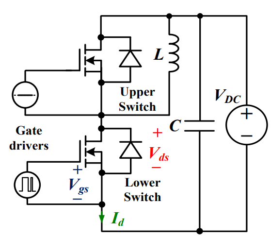 Discovering New and Advanced Methodology for Determining the Dynamic Characterization of Wide Bandgap DevicesSaumitra Jagdale15 March 20242346
For a long era, silicon has stood out as the primary material for fabricating electronic devices due to its affordability, moderate efficiency, and performance capabilities. Despite its widespread use, silicon faces several limitations that render it unsuitable for applications involving high power and elevated temperatures. As technological advancements continue and the industry demands enhanced efficiency from devices, these limitations become increasingly vivid. In the quest for electronic devices that are more potent, efficient, and compact, wide bandgap materials are emerging as a dominant player. Their superiority over silicon in crucial aspects such as efficiency, higher junction temperatures, power density, thinner drift regions, and faster switching speeds positions them as the preferred materials for the future of power electronics.
Read More A Comprehensive Guide to FPGA Development BoardsUTMEL11 September 20257991
This comprehensive guide will take you on a journey through the fascinating world of FPGA development boards. We’ll explore what they are, how they differ from microcontrollers, and most importantly, how to choose the perfect board for your needs. Whether you’re a seasoned engineer or a curious hobbyist, prepare to unlock new possibilities in hardware design and accelerate your projects. We’ll cover everything from budget-friendly options to specialized boards for image processing, delve into popular learning paths, and even provide insights into essential software like Vivado. By the end of this article, you’ll have a clear roadmap to navigate the FPGA landscape and make informed decisions for your next groundbreaking endeavor.
Read More Applications of FPGAs in Artificial Intelligence: A Comprehensive GuideUTMEL29 August 20252201
This comprehensive guide explores FPGAs as powerful AI accelerators that offer distinct advantages over traditional GPUs and CPUs. FPGAs provide reconfigurable hardware that can be customized for specific AI workloads, delivering superior energy efficiency, ultra-low latency, and deterministic performance—particularly valuable for edge AI applications. While GPUs excel at parallel processing for training, FPGAs shine in inference tasks through their adaptability and power optimization. The document covers practical implementation challenges, including development complexity and resource constraints, while highlighting solutions like High-Level Synthesis tools and vendor-specific AI development suites from Intel and AMD/Xilinx. Real-world applications span telecommunications, healthcare, autonomous vehicles, and financial services, demonstrating FPGAs' versatility in mission-critical systems requiring real-time processing and minimal power consumption.
Read More 800G Optical Transceivers: The Guide for AI Data CentersUTMEL24 December 20251030
The complete guide to 800G Optical Transceiver standards (QSFP-DD vs. OSFP). Overcome supply shortages and scale your AI data center with Utmel Electronic.
Read More Xilinx FPGAs: From Getting Started to Advanced Application DevelopmentUTMEL09 September 20252890
This guide is your comprehensive roadmap to understanding and mastering the world of Xilinx FPGA technology. From selecting your first board to deploying advanced AI applications, we'll cover everything you need to know to unlock the potential of these remarkable devices. The global FPGA market is on a significant growth trajectory, expected to expand from USD 8.37 billion in 2025 to USD 17.53 billion by 2035. This surge is fueled by the relentless demand for high-performance, adaptable computing in everything from 5G networks and data centers to autonomous vehicles and the Internet of Things (IoT). This guide will walk you through the key concepts, tools, and products in the Xilinx ecosystem, ensuring you're well-equipped to be a part of this technological revolution.
Read More
Subscribe to Utmel !
![UCC5310MCDR]() UCC5310MCDR
UCC5310MCDRTexas Instruments
![1EDI20H12AHXUMA1]() 1EDI20H12AHXUMA1
1EDI20H12AHXUMA1Infineon Technologies
![1EDI60H12AHXUMA1]() 1EDI60H12AHXUMA1
1EDI60H12AHXUMA1Infineon Technologies
![1EDI30I12MFXUMA1]() 1EDI30I12MFXUMA1
1EDI30I12MFXUMA1Infineon Technologies
![UCC21220DR]() UCC21220DR
UCC21220DRTexas Instruments
![HCS201T-I/SN]() HCS201T-I/SN
HCS201T-I/SNMicrochip Technology
![ADATE305BSVZ]() ADATE305BSVZ
ADATE305BSVZAnalog Devices Inc.
![AD9172BBPZ]() AD9172BBPZ
AD9172BBPZAnalog Devices Inc.
![ADUM4223CRWZ]() ADUM4223CRWZ
ADUM4223CRWZAnalog Devices Inc.
![FM33256B-G]() FM33256B-G
FM33256B-GCypress Semiconductor Corp


